WWW.thanetweather.co.uk

| Broadstairs Weather WWW.thanetweather.co.uk |
|
|
|
PARTS OF A DISSOLVED AIR FLOATATION FILTER
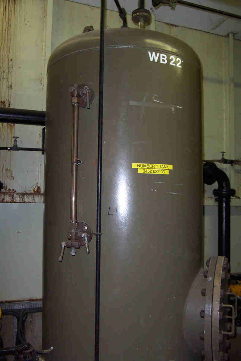
Dispersion vessel or saturator
Dispersion vessel or saturator The first picture shows the dispersion vessel or saturator. This is where the air & water are mixed to produce the dissolved air that is used to create the dispersion that lifts the floc to the surface of the filter
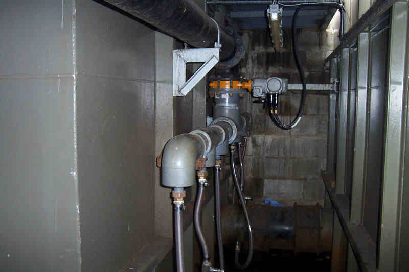
The next picture shows the inlet valve & all the pipework that comes from the dispersion vessel & introduces the dissolved air into the filter
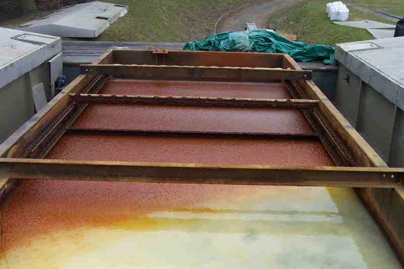
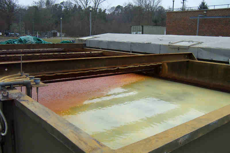
The next pictures show the dissolved air & the floc on the filter This filter is being taken out of service to be refurbished normally the filter has a roof on As you can see from the following pictures the air & water streams down the filter & holds up the iron preventing it from dropping to the bottom of the filter & blocking it.
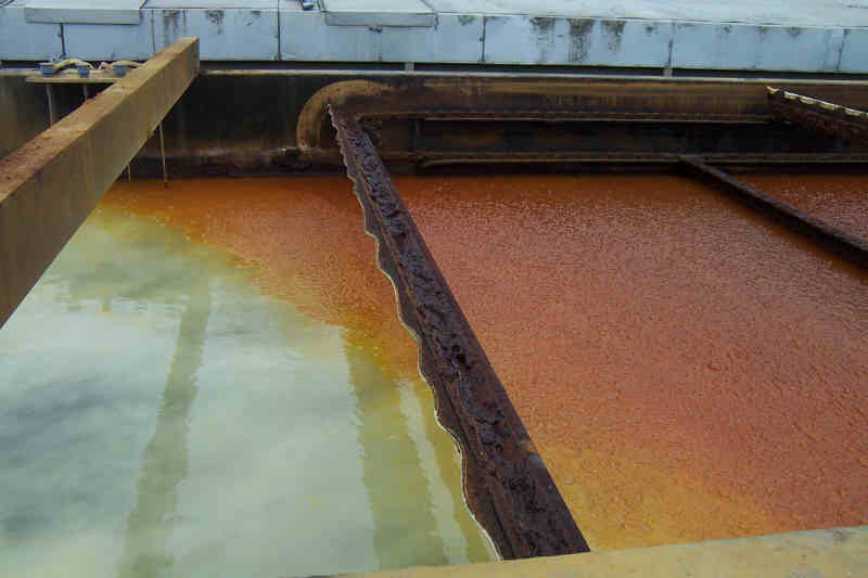
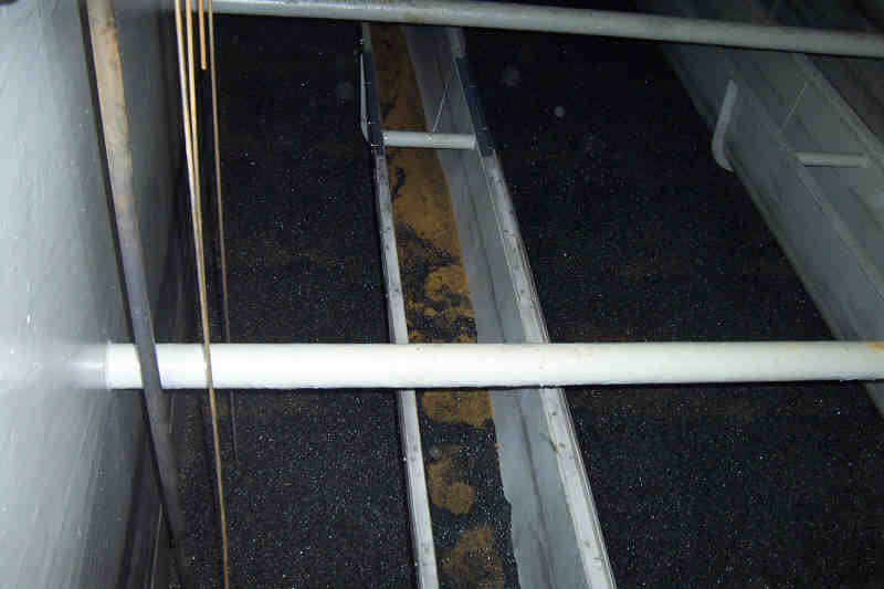
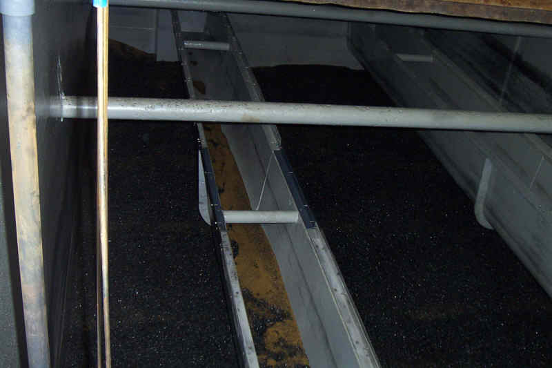
The next photo shows the same process but you can also clearly see the scrapers that remove the iron from the top of the filter
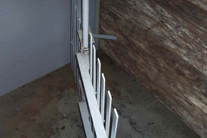
The next pictures show the inside of an empty filter this one
has just been refurbished & is being prepaired for use
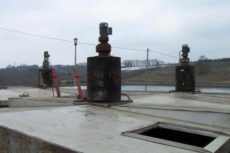
The next pictures show the Floc tank where the ferric & water are mixed. The first picture shows the large mixer in the tank, there are two mixers per filter. The second picture shows the motor & gearbox fixed to the tank this drives the mixer
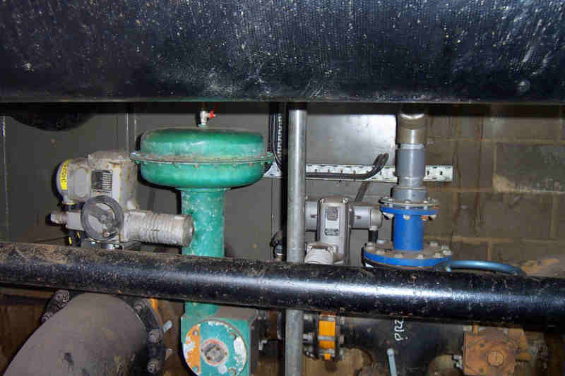
Next we have some pictures of the valves that allow the water in & out of the filter & also control the washing of the filter The valve on the right is the outlet the valve on the left is the washwater inlet
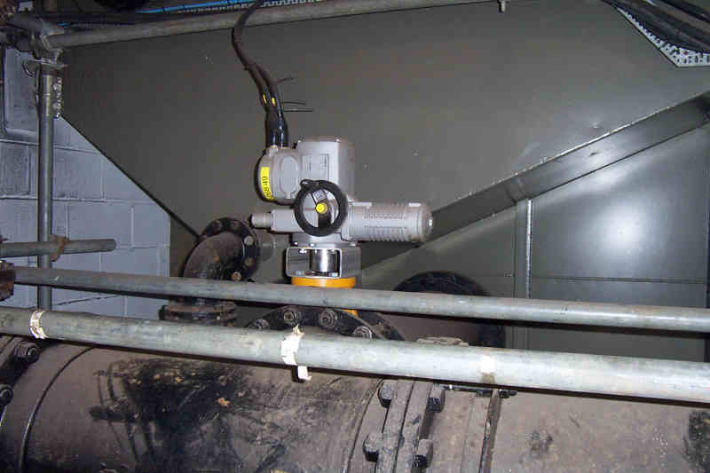
The next photo shows the inlet valve
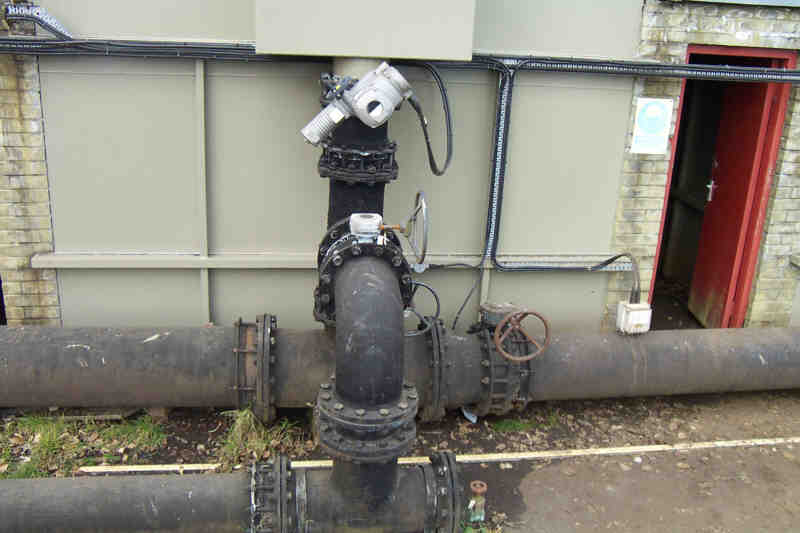
The next picture is the washwater outlet valve this is located above the outlet & wash water inlet valve
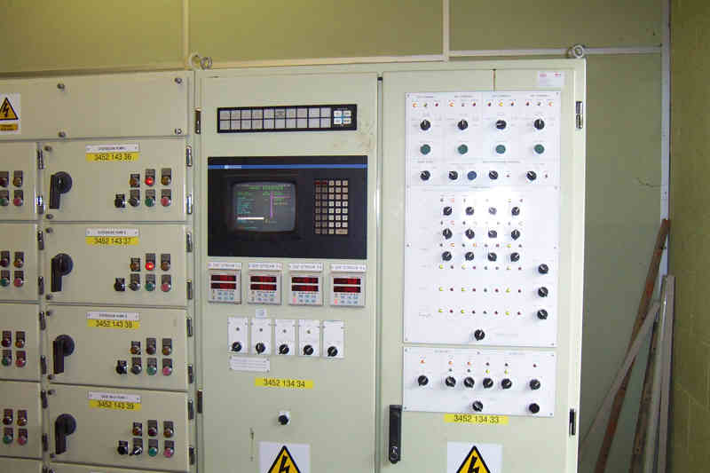
Finally we have the equipment that controls all the processes involved in operating the filter the control panel is all controlled by a plc
|